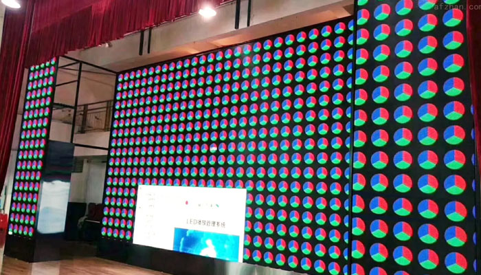
The LED display “mosaic” problem phenomenon has been a problem that has always plagued LED display manufacturers. From the perspective of phenomenon, the “mosaic” phenomenon of LED display shows the inconsistency of the brightness of the display surface in different regions, that is, poor uniformity. The poor uniformity of a full-color LED display includes two aspects: poor brightness uniformity and poor chromaticity uniformity.
Poor uniformity will cause “mottling” or “mosaic”, which will seriously affect the viewing effect of the image. When the wavelength of the lamps used in the same display is the same, the chromaticity uniformity is manifested in two aspects: uniformity and color fidelity. Chromaticity uniformity refers to the color difference between pixels, modules, and modules on the same screen when the same color is displayed; color fidelity refers to the color reproduction between the image on the display screen and the source image or source scene The degree of agreement.
Taking into account the causes and measurement of LED color difference, in order to improve color uniformity and color fidelity, the color difference has to be reduced. There is a special article about this, and there are corresponding equipment to choose to correct. However, the inconsistency of brightness is the most common and difficult to avoid, because it is caused during the manufacturing process, which is a mechanical characteristic, and it is also the root cause of “mosaic”. The correction equipment cannot be used for correction in the later period, so researching and avoiding this problem is the main task of LED display manufacturers.
Note: The reasons in the manufacturing process include the lamp manufacturing and screen manufacturing processes. Because according to the current electronic technology, as long as the error related to the electrical characteristics can be improved in the later correction, but the mechanical characteristics cannot be improved in the later stage, and can only be achieved by the manufacturing process itself.
Causes and solutions of “mosaic”:
As mentioned above, the root cause of the mosaic is caused by the consistency of the lamp itself and the consistency defects during use. We need to explore and analyze the causes and solutions from multiple angles.
1. The size of the up and down and left and right angles of the LED tube is inconsistent
As we all know, the tubes used in conventional LED tube-type displays are usually elliptical tubes. Early LED tube cores have low luminous efficiency. In order to obtain better viewing results, tube manufacturers use optical means and use the habit of human observation to increase the luminous efficiency. Increasing the left and right angle, reducing the up and down angle, and effectively using the amount of light, the result is a large left and right angle, generally 110°, and a small vertical angle, generally only 45°. If the lamp tube is perpendicular to the display screen, the usable angle will not be greater than 22.5°. For example, when the display is 8m high, the bottom edge is 3m above the ground, and the viewing distance is 50m, an angle loss of 8° will be caused. Various tests have proved that in the case of high brightness, an error of 10% can be tolerated. The display is 6°.
2. The up and down angles and left and right angles of the LED tube are not consistent;
There are also differences in the upper and lower angles, left and right angles between the LED tube and the tube. Some researchers have tested the light type of a variety of tubes. Among them, NICHIA and CREE tubes basically meet the specifications of the specifications, and most products exist. The angle difference, for example, the angle is 110°, the left and right angles may not be symmetrically distributed, as shown in Figure 5, such as +30~80°, the same is true for the up and down, it is likely to be 30° up and 15° down, if The selected lamp does have this condition, and the phenomenon of “dark spots” and “spots” will appear.
3. The inconsistency between the angle of the LED tube and the angle of the screen;
Usually, people often interpret the angle of the lamp tube directly as the angle of the display screen. This is somewhat misunderstood. First, the display screen is usually much larger than the lamp, and the direction of the lamp tube is not consistent with the direction of the screen. From the principle of eye observation, the appropriate observation distance should be 2,000 times the pixel pitch or 5 times the diagonal distance, whichever is greater.
4. The angle of each color tube is inconsistent;
From the perspective of the manufacturing process of the LED tube, the shape of the light emitted by the red, green, and blue tubes is inconsistent. In fact, after observation, it is found that only Nichia basically conforms to the light curve provided, and some of the original products of CREE can. Therefore, if a lamp with poor consistency of the three-color light shape is used, the phenomenon of “dirty spots” and “spots” will also appear.
Reasons when using LED lights:
The reason why the LED lamp is used is the most concerned issue of the LED display manufacturer, the main task of the manufacturer, and the main basis for reflecting the manufacturer’s technical level, management level, production scale and market composition.
Attention should be paid to LED uniformity selection, angle selection, lamp direction correction, kit design, cabinet design, and external structure design.
1. The choice of LED display:
Try to use the same brand, the same model, and the same grade of LEDs. The more consistent the lamp, the more expensive the price, you must first choose the lamp with good angle consistency;
2. Angle selection of LED display:
Try to choose a large angle, especially the LED with a large upper and lower angle. The angle of the LED is usually selected according to the requirements of the actual use for the angle of the LED display. The smaller the angle, the higher the brightness. When making the display screen, some companies have to reduce the left and right, or even the up and down angles in order to meet the forward brightness requirements, so choose the angle according to the actual situation. And the lamp tube with a big up and down angle.
For squares, long-distance viewing screens can choose light tubes with large left and right angles and small vertical angles. If the situation is like “looking across the river” at the scene, you can choose a slightly smaller top and bottom, left and right. . For those with high height and close distance, you can choose a round lamp with a large angle or choose a surface mount lamp;
3. Calibration of LED lights:
After the lamp and lamp angle are determined, the LED lamp calibration mentioned here means to ensure that the LED lamp tube and the surface of the screen are perpendicular or at a certain angle. For this reason, necessary and effective measures must be taken for the lamp tube before, during and after welding. The lamp tube should be mixed before welding. After the lamp tube is inserted into the unit board, it needs to be fastened with a clamp. The clamp style is shown in Figure 6. Do not loosen or fall off during the welding process. After welding, take out the lamp board gently until it is installed inside the module. Do not touch the lamp tube. Before the lamp is filled with glue, check whether it meets the requirements of the lamp angle;
4. Kit design:
Kits refer to various types of modules commonly used in display screens, including bottom shells and masks. The bottom shells must have a certain degree of flatness, strength, and durability. Under the pressure of cost, the current PC plastic kit will incorporate a lot of fillers, and the characteristics will be lost. The most important thing here is the flatness. The flatness is required to be less than 1:200. The reasons have been mentioned above. For this reason, it is necessary to strictly consider the height deviation of the PCB into the bottom case and the fixing of the module to the box body. Due to the waterproof rubber pad between the bottom case and the box body, the module will be uneven due to the different strength of the fastening screws. . Otherwise, there will be a “mosaic” phenomenon in units of modules.
For the mask, the tube hole must be in close contact with the tube to further fix it; it must have a certain strength to protect the tube from impact; it must have a good optical design to minimize sunlight reflection , It can improve the contrast; the brim of the hat is guaranteed to have a certain height, which can protect the lamp tube and prevent sunlight. The purpose is to let the light shine between the lamp tube and the lamp tube without affecting each other; the smaller the thermal deformation, the better, including self-heating and the influence of sunlight.
“Kit design” means that the kit used must be carefully considered for the above factors, suitable for the lamp used in this screen and other additional requirements. The “public version” module is commonly used in the market, resulting in the lamp and the module The mask is severely mismatched. The public version of the module is suitable for all kinds of lamps, and it must be large enough. Once used, it will inevitably cause the lamp to be “crooked”. If there is no problem if it is used, it is purely coincidental, and most of them have not considered the need to combine with the cabinet.
Therefore, once the use method of the display screen is determined, a special module needs to be specially designed. For successful cases, for example: the display screen produced by Konka in Beijing Pangu Building, the module is designed for a special project;
5. Module filling:
After the outdoor screen light board is installed in the module, it is necessary to add sealant for waterproofing. Because black potting glue is usually used, the final brightness of the display will be affected by the height of the glue surface. Generally, the glue surface error between modules is less than 0.3mm, and the levelness is better than one thousandth.
In the module structure, the glue surface height requires that the glue surface cover all the metal parts of the lamp pin during glue filling; usually the glue filling height is based on not exceeding the mask pillar (hereinafter referred to as the mask column) in the module, and the glue surface is offset downward. , The distance from the height of the rubber surface to the cover column is not more than 0.3mm;
The requirements for the flatness of the box and the guarantee of the flatness are from beginning to end. The front of the box must be parallel to the fixed surface of the box. Therefore, the flatness of the display box must be better than five thousandths after the completion of the display box.
At present, most of the cabinets used are sheet metal technology, using cold-rolled steel or aluminum plates. In order to meet the above process requirements, it is necessary to ensure that the cabinet panel and the cabinet are not deformed during use. For this reason, when designing the back ribs of all boxes, attention must be paid: the modules must be equipped with reinforcing ribs, and the cross-section is shown in Figure 8, where the width of W must be greater than 15mm, and the height of H changes with the length of the rib, and each joint must ensure reliable welding. There are 3 points on each side of each fillet solder joint, a total of 36 solder joints, must not be missing. There must be at least 3 welding points for each distance between the welding part of the rib and the panel.
The above reinforcement method can ensure that the box surface is not deformed when loaded with a 100kg box on an area of 300×300mm. At present, the design of sheet metal cabinets is generally “with ribs and no bones”. Unless the cabinet needs to be hoisted, the cabinet frame is not set. It needs to be considered in the design and installation of the external structure. Do not stack the cabinets one by one;
7. Power supply design:
The low-voltage power supply design in the display unit box is to ensure the constant LED working current from the electrical characteristics. For full-color displays, most of them use constant current drive chips. Whether the constant current characteristic of the constant current chip is stable and effectively controlled determines the adaptability to load changes. For a certain constant current chip, different constant current currents will have a voltage value that enters the constant current. If the control chip outputs a constant current at 20mA, it must be ensured that VDS is greater than 0.5V, and 30mA must be guaranteed to be greater than 0.7V.
Changes in load and power supply may cause the chip to enter the amplification area and lose its constant current function. For example: when two red light tubes are used in series in a full-color screen, when the red, green and blue are all on, the load current of the wire increases, the voltage drop increases, and the working voltage of the power board decreases, causing the constant current drive chip to enter the amplification area. The current drops, the brightness decreases, and the screen body is color cast. Some chips may actually be different from the specifications and need to be verified so that they can be avoided in actual use.
For wires with too long wiring inside the box, it is likely to cause excessive voltage drop loss. In the case of low voltage 5V, it cannot be used in accordance with the safe current of electricians. Take 2.5mm2 wire as an example, the resistance per meter is 7.44mΩ, The electrician’s safe current value is about 28A. If you have two 10A modules, consider the case of using only one meter of wire. Not less than 4.8V, this is a very harsh condition, if the wire is further lengthened, the problem will be more serious.
It shows that there is no problem when the display is low-brightness. When the display is completely white, there will be some module color deviations. Generally, it is a solid-point full-color screen used in series with two lights. When the display is completely white, the red will not light up;
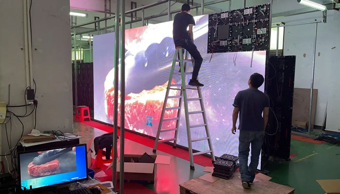
8. Module installation:
During the installation process of the module, it must be ensured that the lamp tube of the module is not impacted by external force and the module must be installed evenly and flatly on the box body. Therefore, the installation process must be completed in a dedicated tooling, as shown in Figure 9. A torque wrench is used to make the necessary torque for tightening consistent. After installation, a special measuring tool is required for measurement and inspection. If it does not meet the requirements, it needs to be adjusted to the leveling standard;
9. Packaging and transportation of the screen:
The display screen is also an easily overlooked link from the production of the manufacturer to the installation site. Many factors mentioned above are aimed at ensuring the flatness and verticality of the display tube. After the display unit box is assembled, it must be properly packaged, and the box must be made. Arranged vertically, the packaging box must really play a protective role to prevent the screen from being deformed by the impact of hard objects. If conditions permit, the transfer tooling frame should be set up as shown in Figure 10.
If the box body needs to be stacked during transportation, the stacking load must be handled well, and the box body must not be directly pressed and the shape of the box body must be changed. In practice, the author has repeatedly found that the screen tested in the factory has deteriorated after being installed after the transfer process. In addition to the box itself, negligence in the transfer is also one of the important reasons;
10. External structure design and installation:
Finally, the display screen needs to be installed on the steel structure to form a whole. In the design and construction of the external structure, the installation plane of the display screen should also be kept flat and stable. At the same time, the design of the installation structure should ensure that the single box does not sag, deform, There should be a gap between the pressure, the upper and lower boxes, the left and right boxes, and the weight of the box itself is directly transferred to the steel structure.
Conclusion:
To sum up, the “mosaic” phenomenon of LED display is a systematic comprehensive problem. It is the most fundamental solution to ensure the flatness of the lamp in each link of lamp and screen production. Any subsequent “brightness and chromaticity” correction The main premise is that a qualified display screen can be produced in accordance with the standard.